
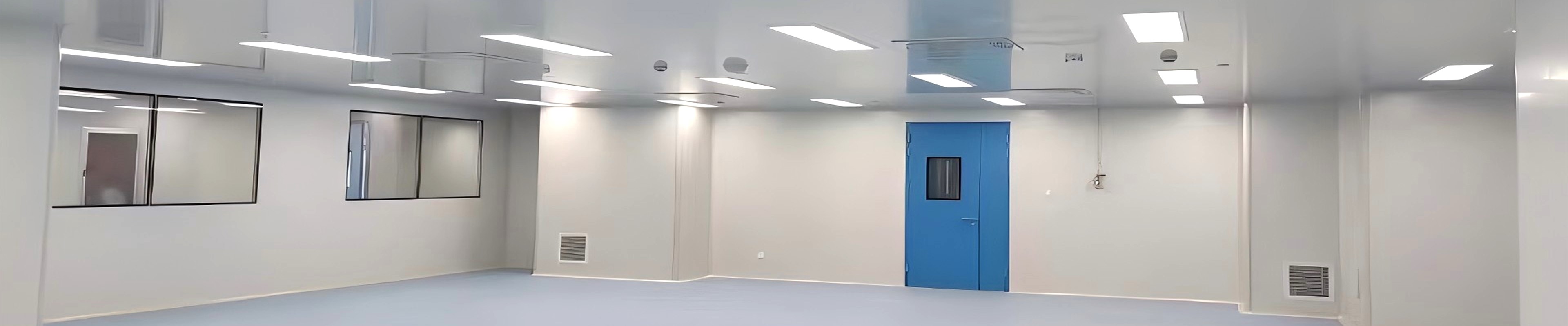
Stable cleanroom conditions do not start at the ceiling or the wall panel. They start at the cold source — the equipment that removes heat from the chilled water circuit that cools and dehumidifies the air entering the cleanroom. Without a reliable chiller providing stable, cold water at the right temperature and flow rate, the best-designed air-handling unit cannot maintain the 20-26 degrees C and 45-65% RH conditions that pharmaceutical, laboratory, and electronics cleanrooms require.
SCT's air-cooled chiller supports HVAC temperature and relative humidity control across different cleanroom application sectors, from pharmaceuticals and laboratories to electronics, hospitals, food, and medical-device facilities. This article explains what an air-cooled chiller does in a cleanroom HVAC system, how to specify one correctly, and how its performance maps to the environmental conditions your cleanroom needs to maintain.
1. The Chiller's Role in the Cleanroom HVAC System
A cleanroom HVAC system is a closed thermal loop. The air-handling unit (AHU) conditions air — cooling it, dehumidifying it, reheating it, and humidifying it — and distributes it through the cleanroom. To cool and dehumidify that air, the AHU needs a source of cold water. That cold water is supplied by the chiller.
The chiller removes heat from the chilled water circuit and rejects it to the outdoor air. In an air-cooled system, this rejection happens through a finned-coil heat exchanger and fan array — no cooling tower, no water consumption, no water-treatment complexity. This makes air-cooled chillers the preferred choice for most cleanroom installations, particularly in regions where water is expensive or regulated.
The quality of the cold source — its temperature stability, its capacity, and its reliability — directly determines the quality of the air conditions in the cleanroom. A chiller that drifts +/- 2 degrees C on its leaving water temperature will produce an AHU that cannot hold +/- 1 degree C on the room temperature, regardless of how sophisticated the AHU controls are.
2. Why Temperature and Humidity Stability Matters More Than You Think
Cleanroom temperature and humidity are not cosmetic comfort parameters. In most cleanroom applications, they are process parameters — and process parameter deviations have consequences.
| Application | Typical Conditions | Why It Matters |
| Pharmaceutical GMP (Grade A-D) | Temperature: 20-24 degrees C (Grade A-C); 18-26 degrees C (Grade D) Relative Humidity: 45-60% (Grade A-C); 45-65% (Grade D) EU GMP Annex 1 requires validated environmental conditions. |
Out-of-spec RH promotes microbial growth; temperature excursions affect product stability and personnel comfort. |
| Electronics / semiconductor | Temperature: 20-26 degrees C Relative Humidity: 30-50% (typically 35-45% for wafer fab) Low humidity prevents static charge accumulation; high humidity causes condensation on components. |
RH below 30% generates static discharge (ESD); RH above 55% causes condensation on chilled surfaces. |
| Medical device manufacturing | Temperature: 20-24 degrees C Relative Humidity: 45-65% |
Humidity affects material properties (plastics, adhesives) and personnel performance during precision assembly. |
| Hospital / sterile compounding | Temperature: 20-24 degrees C Relative Humidity: 45-65% USP <797> / EU GMP Annex 1 specify these ranges for aseptic compounding. |
Out-of-spec conditions increase contamination risk during open manipulations. |
In each of these cases, the chiller is the foundational component that makes the specified conditions achievable. Its leaving water temperature stability — typically +/- 0.5 to 1.0 degree C for a quality chiller — is the starting point for whatever temperature control accuracy the cleanroom process requires.
3. Air-Cooled vs Water-Cooled Chiller for Cleanrooms
The choice between an air-cooled and a water-cooled chiller is determined primarily by the site conditions and the cooling demand profile. For most cleanroom applications, air-cooled is the preferred option. Here is why.
| Criteria | Air-Cooled | Water-Cooled |
| Cooling tower required | No: rejects heat via fan-cooled condenser coils | Yes: requires separate cooling tower, pump, and water treatment system |
| Water consumption | Minimal: only condensate drainage | Significant: evaporative losses require ongoing makeup water and blowdown management |
| Installation complexity | Lower: packaged unit, single connection to chilled water circuit | Higher: chiller, cooling tower, pumps, and pipework require separate installation coordination |
| Maintenance | Condenser coil cleaning, fan motor inspection, refrigerant charge | Cooling tower water treatment, scale/biofilm management, pump seals |
| Site suitability | Preferred for most cleanrooms; requires adequate outdoor air for condenser airflow | Required for large cooling loads (>500 kW) or where ambient temperatures are consistently high (>40 degrees C) |
| Cleanroom HVAC scale | Typical range 50-500 kW per unit — covers most cleanroom AHU loads | More common in large industrial facilities with existing cooling tower infrastructure |
For cleanroom applications — where the AHU load is typically in the 50-500 kW range per unit — an air-cooled chiller is almost always the right choice. It avoids the water management complexity of a cooling tower, installs in a single package, and provides reliable cooling for the cleanroom's operating life.
4. Key Chiller Specifications for Cleanroom Applications
When specifying an air-cooled chiller for a cleanroom HVAC system, the following parameters directly affect the environmental conditions the system can achieve.
• Leaving water temperature (LWT) and stability. The chilled water temperature leaving the chiller — typically 6-8 degrees C for comfort cooling — must be stable within +/- 0.5 to 1.0 degree C. Chillers with poor LWT stability will produce AHU coil leaving air temperatures that drift, making precise room temperature control impossible regardless of the AHU control system.
• Cooling capacity (kW). The chiller capacity must match the peak AHU cooling load with an appropriate margin (typically 10-15% above the design load). Undersizing produces temperatures that rise during peak summer conditions or when additional process heat loads are introduced. Oversizing reduces part-load efficiency and can cause short-cycling.
• Part-load performance (EER / IPLV). Cleanrooms rarely run at design load — occupancy varies, equipment cycles, and seasons change. The Integrated Part Load Value (IPLV) or European Seasonal Energy Efficiency Ratio (ESEER) characterises the chiller's efficiency under part-load conditions. A higher IPLV means lower energy consumption during normal operation.
• Ambient temperature operating range. The chiller must operate reliably at the highest expected outdoor dry-bulb temperature for the site location. For most temperate climates, standard units are rated to 40-45 degrees C. In hot climates or rooftop installations, confirm the unit's actual capacity at the design ambient — not just its nominal rating at standard conditions.
• Refrigerant type and GWP. Current refrigerants (R-410A, R-32) have relatively low Global Warming Potential compared to older HFC blends. Confirm the refrigerant meets your facility's environmental policy and any local F-gas regulation requirements. Lower-GWP refrigerants (R-1234ze) are increasingly available for new installations.
5. Integration with Cleanroom AHU and BMS
The chiller does not operate in isolation. Its performance is fully determined by how well it integrates with the AHU and the building management system (BMS).
• Chilled water circuit. The chiller connects to the AHU via a primary chilled water circuit. A primary/secondary decoupling arrangement — where the chiller pump operates at constant flow and the AHU pumps operate at variable flow — is the standard configuration for cleanroom HVAC, allowing the AHU to modulate its cooling output without disturbing the chiller's stable operating conditions.
• BMS integration. Modern chillers communicate via Modbus, BACnet, or LonWorks protocols. Key data available at the BMS includes: leaving and return water temperatures, refrigerant pressures, compressor status and run-hours, fault codes, and current power consumption. This data enables remote monitoring, predictive maintenance scheduling, and energy reporting for regulatory compliance.
• Standby and redundancy. For critical cleanroom applications (pharmaceutical Grade A/B, semiconductor ISO 5), a standby chiller or N+1 configuration ensures continuity if the primary unit trips. The BMS manages the automatic transfer to standby and the controlled restart sequence after a fault is cleared.
6. Applications by Industry
| Industry | Why Air-Cooled Chiller | Typical Configuration |
| Pharmaceutical GMP (Grade A-D) | Chiller provides stable cold water for AHU cooling and dehumidification. Precise LWT stability (+/- 0.5 degree C) is required for validated temperature control. BMS integration supports 21 CFR Part 11 electronic records. | Typically 2-4 units with N+1 redundancy for Grade A/B suites |
| Electronics / semiconductor | Low relative humidity (35-45% RH) requires deep dehumidification. Chiller must provide cold water stable enough to support the dry-coil dehumidification strategy without overcooling. | High-capacity units (500+ kW) for large fab cleanrooms; standby chiller is standard |
| Hospital / sterile compounding | Consistent 20-24 degrees C, 45-65% RH is maintained year-round. Air-cooled units avoid Legionella risk associated with cooling towers. Simpler maintenance profile is an advantage in hospital environments. | Typically 2 units for redundancy; BMS integration with hospital automation system |
| Medical device manufacturing | Cleanrooms operate at steady-state conditions for most of the year. Part-load efficiency (IPLV) is the key operating cost driver. Air-cooled units with EC fans offer good part-load efficiency. | Medium-capacity units (100-300 kW) with N+1 configuration |
| Food processing (high-care zones) | Temperature and humidity control for aseptic filling and high-care zones. Air-cooled units avoid cooling tower water management in food-processing hygiene environments. | Compact footprint air-cooled units suitable for rooftop or external ground installation |
7. Maintenance and Operating Cost Considerations
• Condenser coil cleaning (6-12 months). Air-cooled condensers accumulate dust, pollen, and debris on the finned coils, reducing heat rejection capacity and increasing compressor discharge pressure. Annual coil cleaning restores capacity and reduces power consumption. In dusty or industrial environments, cleaning intervals should be shortened.
• Fan motor and ECM driver inspection (annual). Inspect fan motor bearings, check ECM driver parameters, and verify fan airflow is within specification. Abnormal vibration or noise indicates bearing wear that should be addressed before failure.
• Refrigerant leak checking (annual, per F-gas regulation). Annual refrigerant leak checking is required by EU F-gas Regulation (517/2014) for systems with refrigerant charge above threshold quantities. Automatic leak detection systems are available and reduce the burden of manual checking.
• Operating cost profile. Chiller energy is typically 30-50% of the total HVAC energy bill in a cleanroom facility. Selecting a chiller with a high IPLV and integrating it with the BMS for setpoint optimisation — raising the leaving water temperature setpoint during part-load conditions — can reduce annual chiller energy consumption by 15-25% compared to a fixed-setpoint operation.
8. Frequently Asked Questions
Answers for cleanroom engineers, MEP designers, and facility managers.
Q: What is an air-cooled chiller and how does it work in a cleanroom HVAC system?
A: An air-cooled chiller removes heat from a chilled water circuit using a refrigerant cycle, rejecting the heat to outdoor air through a finned-coil condenser with fans. The chilled water is then circulated to the AHU, which uses it to cool and dehumidify the air entering the cleanroom. The chiller is the cold source — the foundational component that makes the AHU's temperature and humidity control possible.
Q: Why is an air-cooled chiller preferred for most cleanroom applications?
A: Air-cooled chillers avoid the water management complexity of cooling towers — no Legionella risk, no ongoing water treatment, no makeup water costs. For the typical cooling load range of cleanroom AHUs (50-500 kW per unit), air-cooled units are the standard choice. They install as a single packaged unit, connect to the chilled water circuit, and require only condensate drainage.
Q: What chiller specifications matter most for cleanroom temperature and humidity control?
A: Leaving water temperature (LWT) stability is the most critical specification — a chiller that drifts +/- 2 degrees C on LWT will make it impossible to hold +/- 1 degree C in the room. Cooling capacity must match peak load with 10-15% margin. Part-load performance (IPLV/ESEER) determines operating cost across the year. And the ambient temperature operating range must cover the highest expected outdoor temperature at the site location, not just standard test conditions.
Q: How does a chiller integrate with the cleanroom BMS?
A: Modern chillers communicate via Modbus, BACnet, or LonWorks protocols, sending data to the BMS on water temperatures, refrigerant pressures, compressor status, faults, and power consumption. The BMS uses this data to optimise chiller operation (setpoint, sequencing, standby transfer), log operating conditions for regulatory records, and trigger maintenance alerts when parameters approach limits.
Q: How does chiller performance affect cleanroom humidity control?
A: Humidity control in an AHU is achieved by cooling the air below its dew point (dehumidification) and then reheating it to the desired supply temperature. The chiller's leaving water temperature stability directly determines how precisely the AHU can achieve this cooling and reheat cycle. A chiller with poor LWT stability produces AHU leaving air temperatures that drift, which translates directly into room humidity that swings beyond specification.
9. Why SCT for Cleanroom HVAC Chiller Systems?
• Cleanroom HVAC as an integrated system. SCT supplies the chiller as part of the same cleanroom HVAC system as the AHU, air shower, pass box, and ceiling grid — so the chiller capacity, AHU coil load, and controls are all matched in the engineering design stage, not reconciled between separate suppliers on site.
• Application-matched capacity planning. SCT's engineering team sizes the chiller to the cleanroom's specific peak load, ambient conditions, and redundancy requirement. This means the chiller is not oversized (wasted capital and part-load inefficiency) or undersized (failure to maintain conditions on the hottest design day).
• CE certification and documentation. Every SCT chiller ships with CE Declaration of Conformity, performance test data, and dimensional drawings for the project qualification file. For GMP applications, the chiller documentation integrates with the overall HVAC qualification package.
The Cold Source Is the Foundation
Every cleanroom's temperature and humidity conditions are only as good as the cold source that supplies them. An air-cooled chiller that is correctly sized, stable in its leaving water temperature, and properly integrated with the AHU and BMS is the foundation on which the cleanroom's validated environmental conditions are built. Cut corners on the chiller, and the best AHU, best filters, and best ceiling system will not compensate for rooms that drift out of specification on the warmest design day.
SCT supplies air-cooled chillers as part of complete cleanroom HVAC systems — matched to your AHU load, site ambient conditions, and redundancy requirements, with full documentation for GMP and ISO 14644 qualification files. Contact SCT to discuss your cleanroom HVAC chiller specification.
Contact SCT Cleanroom
Website: www.sctcleanroom.com
Email: admin@sctcleanroom.com
WhatsApp: +86 15306200553
Post time: Sep-30-2026