
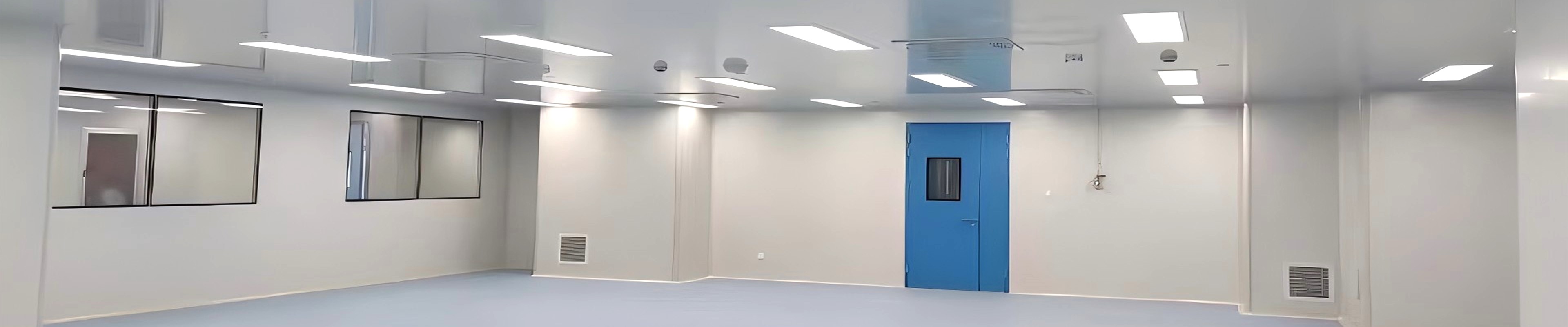
Walk onto the ceiling of a modern modular cleanroom and you will see a grid of identical modules — each one a self-contained unit that draws air from the plenum, pushes it through a HEPA filter, and discharges clean, unidirectional airflow directly into the classified room below. That module is the Fan Filter Unit, or FFU. It is the building block of a modular cleanroom ceiling, the component that makes the cleanroom a cleanroom at the most fundamental level.
SCT's Fan Filter Unit combines air circulation and HEPA filtration in one compact ceiling-mounted solution, delivering clean, uniform airflow directly to critical working areas. This guide explains how an FFU ceiling system works, how to plan the layout, and what to specify for a compliant, efficient installation across pharmaceutical, electronics, laboratory, hospital, food, and medical-device applications.
1. What Makes an FFU Different: Self-Contained Airflow at the Ceiling
The most important thing to understand about an FFU is that it is self-powered. Unlike a HEPA box, which relies on ducted supply pressure from a central air-handling unit, an FFU contains its own motorised fan that draws air from the plenum, pushes it through the HEPA filter, and discharges it into the room — all without any ductwork connection. This architectural difference has profound consequences for how a cleanroom ceiling is designed, operated, and modified.
Because each FFU generates its own airflow, the ceiling becomes a modular array of independent air-supply points. If one FFU fails, the adjacent units continue operating — there is no single point of failure that brings down the entire ceiling. If the room layout changes, FFUs can be relocated within the grid. If the cleanliness class needs to be upgraded, the filter grade in each FFU can be changed independently. This flexibility is what makes the FFU ceiling the dominant architecture for modular cleanrooms worldwide.
2. Inside an FFU: Components and How They Work Together
A ceiling-mounted FFU contains five functional layers, stacked from plenum to room:
• Fan section — ECM motor and backward-curved impeller. The motor is almost universally an Electronically Commutated Motor (ECM) in modern FFUs. ECM motors are highly efficient, compact, and controllable via 0-10V or PWM signal, allowing each FFU airflow rate to be adjusted individually for precise air-balance.
• Pre-filter (G4). A coarse pre-filter upstream of the fan protects the HEPA filter from large particles and extends HEPA service life. Pre-filters are replaceable from the room side without tools, typically every 1-3 months depending on site conditions.
• HEPA filter (H13/H14, optionally U15/U16). H13 (>=99.99% at 0.3 micrometre) is standard for ISO 5-8; H14 (>=99.995%) for ISO 5 and cleaner. Mini-pleat design with gel-seal or gasket interface. ULPA grades U15/U16 available for semiconductor ISO 3-4 applications.
• Diffuser and plenum collar. The diffuser plate at the room face distributes filtered airflow evenly, converting the high-velocity jet into uniform, low-turbulence unidirectional downflow. The plenum collar connects the FFU to the ceiling grid and seals against the ceiling plane.
• Control interface. Each FFU accepts 0-10V or PWM speed signal. Individual status — running/stopped, filter loading, fault — is visible at a central BMS station when integrated.
3. FFU vs HEPA Box: Choosing the Right Ceiling Architecture
The choice between an FFU ceiling and a ducted HEPA box system is one of the most consequential decisions in cleanroom design. The comparison table below maps the key trade-offs.
| Criteria | FFU | Ducted HEPA Box |
| Air source | Self-powered: ECM motor in each unit | Ducted: central AHU differential pressure |
| Ceiling architecture | Modular grid of independent units | Fixed ducted distribution with terminal filter boxes |
| Air-balance adjustment | Individual FFU speed control — precise and fast | Requires damper adjustment or AHU rebalancing |
| Failure mode | Individual FFU failure affects local zone only | AHU or duct failure can bring down entire ceiling |
| Energy consumption | Higher total (fan motor per unit) | Lower total (single central fan) |
| Modification / relocation | FFU relocatable within grid; filter grade changed per unit | Fixed duct routing; changes require ductwork modification |
| Best for | Modular cleanrooms; ISO 5-8; facilities expecting layout changes | Centralised HVAC; large stable zones; retrofits with existing AHU capacity |
The decisive factor is often whether the facility expects to change its layout over time. A semiconductor cleanroom that will be retooled every two years needs an FFU ceiling. A GMP pharmaceutical suite with a fixed process layout and dedicated AHU may find a ducted HEPA box system more energy-efficient. Many large facilities use both — FFU for the main cleanroom and HEPA boxes for stable service areas.
4. Planning the FFU Ceiling Layout
An FFU ceiling is only as good as its layout. A poorly planned array will not achieve the target cleanliness class regardless of how good each individual FFU is. Layout planning follows three steps:
• Step 1 — Calculate the air-change rate. The target cleanliness class determines the minimum air-change rate per hour (ACH). For ISO 8, 20-40 ACH; for ISO 7, 40-60 ACH; for ISO 6, 60-90 ACH; for ISO 5, 90-150+ ACH. Total airflow = Room Volume x ACH.
• Step 2 — Size the FFU array. Each FFU has a defined nominal airflow (typically 500-1,200 m3/h per unit). Divide total airflow by unit airflow to get FFU count. FFU spacing should not exceed 1.2 m centre-to-centre for ISO 5-7, or 1.5 m for ISO 8.
• Step 3 — Account for non-uniform loads. Equipment heat loads, personnel density, and door openings create local variations. Concentrate FFU density over high-heat-load equipment and ensure unobstructed return air paths. CFD modelling is recommended for ISO 5 and ISO 6 cleanrooms.
5. ECM Motor Control: The Technology Behind FFU Arrays
• Individual speed control. Each ECM FFU accepts a 0-10V or PWM speed signal. The BMS or dedicated controller tunes airflow to the room actual load — not a nominal design condition — and idles at reduced speed during unoccupied periods.
• Energy savings from variable-speed operation. Fan power varies with the cube of speed. Reducing FFU speed by 20% cuts power consumption by approximately 50%. A BMS-integrated FFU array modulating speed by occupancy and load delivers substantial energy savings compared to fixed-speed continuous operation.
• Centralised monitoring and alarm. When integrated with a BMS, each FFU status is visible at a central operator station. A rise in differential pressure across the HEPA filter triggers a maintenance alarm pinpointing the specific unit — replacing manual pressure-gauge inspection of every ceiling unit.
6. Applications Across Industries
| Industry | Why FFU | Typical Configuration |
| Semiconductor / electronics (ISO 3-6) | High ACH; frequent layout changes; ISO 3-5 zones require U15/U16 options; ECM speed control reduces energy during low-occupancy periods. | FFU ceiling is the global standard for semiconductor fabs |
| Pharmaceutical (ISO 5-8 / GMP Grade A-D) | Grade A requires ULPA (U15/U16); modular ceiling allows reconfiguration for different product campaigns; BMS integration supports 21 CFR Part 11 records. | FFU for ISO 5-7 primary zones; HEPA box for stable service areas |
| Hospital (negative-pressure isolation, OR) | Individual FFU control enables zone isolation — one room taken out of service without affecting adjacent zones. | SCT provides FFU with negative-pressure configuration for hospital applications |
| Research laboratories | Variable occupancy and changing equipment loads make ECM speed modulation particularly valuable. | Common in university research facilities and contract research organisations |
| Food processing (high-care zones) | ISO 7-8 with moderate cost pressure; phased installation possible — add FFUs zone by zone as budget allows. | Popular in aseptic food processing and high-care dairy facilities |
7. Maintenance: HEPA Replacement and FFU Servicing
• Pre-filter replacement (1-3 months). G4 pre-filters replaced from the room side without tools. Frequency depends on site air quality; dusty environments need more frequent changes. Clogged pre-filters reduce airflow and increase motor load.
• HEPA filter replacement (1-3 years, by differential pressure). Replace when differential pressure reaches approximately 2x the initial (clean) reading — typically 400-500 Pa for H13/H14. HEPA replacement requires FFU removal from ceiling grid; some units support filter replacement from the room side in situ.
• Fan motor inspection (annual). ECM motors are generally maintenance-free but annual inspection should confirm expected speed (verify against BMS reading), clean and balanced impeller, and secure electrical connections.
• Differential pressure monitoring. Advanced units feature built-in DP sensors with BMS output. For standard units, use a portable manometer. Set maximum DP alarm at 2x initial resistance to trigger replacement before performance degrades.
8. Frequently Asked Questions
Answers for cleanroom engineers, MEP designers, and facility managers.
Q: What is a fan filter unit (FFU)?
A: An FFU is a ceiling-mounted device that combines a motorised fan and a HEPA filter in a single self-contained module. It draws air from the plenum, filters it through the HEPA, and discharges clean unidirectional airflow directly into the cleanroom. Unlike a ducted HEPA box, an FFU generates its own airflow without relying on central AHU pressure.
Q: What is the difference between an FFU and a HEPA box?
A: A HEPA box is a passive terminal filter relying on ducted supply pressure from the central AHU. An FFU contains its own ECM motor and fan, making it self-powered and individually controllable. HEPA boxes are more energy-efficient for stable large-zone applications with fixed layouts. FFUs offer superior flexibility and fault isolation for modular cleanrooms.
Q: What HEPA filter grade does an FFU use?
A: H13 (>=99.99% at 0.3 micrometre) is standard for most ISO 5-8 cleanrooms. H14 (>=99.995%) is used for ISO 5 zones and above. Semiconductor fabs requiring ISO 3-4 may specify U15 or U16 (ULPA) filtration. Filter grade should match the cleanliness class of the zone served.
Q: How is an FFU ceiling layout planned?
A: Layout is determined by three inputs: target cleanliness class (drives air-change rate), FFU unit airflow (typically 500-1,200 m3/h), and room dimensions. FFU spacing should not exceed 1.2 m centre-to-centre for ISO 5-7 zones. CFD modelling is recommended for ISO 5 and ISO 6.
Q: How energy-efficient are FFU ceiling systems?
A: Modern ECM-motor FFUs are significantly more efficient than AC-motor predecessors. Fan power varies with the cube of speed — reducing FFU speed by 20% cuts power by approximately 50%. A BMS-integrated FFU array modulating speed by occupancy and load delivers substantial energy savings compared to fixed-speed continuous operation.
9. Why SCT Cleanroom for FFU Ceiling Systems?
• Complete FFU range with ECM motor standard. SCT FFUs use ECM motors as standard, with individual speed control and BMS integration. H13, H14, U15, and U16 filter grades are available to match any cleanroom classification from ISO 8 to ISO 3.
• Integrated ceiling system design. SCT supplies FFU alongside modular wall panels, ceiling panels, doors, windows, and HVAC equipment — so the FFU grid, ceiling grid, and wall envelope are all designed to fit together from a single engineering source.
• CE-certified with full documentation. Every FFU ships with CE Declaration of Conformity, HEPA filter integrity test certificates, material certificates, and dimensional drawings for cleanroom qualification files.
Design the Ceiling Around the FFU
An FFU ceiling is not a collection of individual fans bolted to a grid. It is an integrated air-distribution system — one where every unit is independently controllable, independently maintainable, and independently replaceable. That modularity is the reason it has become the dominant ceiling architecture for cleanrooms that need to adapt, grow, and respond to changing requirements over their operating life.
SCT supplies complete FFU ceiling systems — units, grid, controls, and integration with wall panels, doors, windows, and HVAC — from a single engineering source. Contact SCT to discuss your cleanroom layout, target classification, and FFU array specification.
Contact SCT Cleanroom
Website: www.sctcleanroom.com
Email: admin@sctcleanroom.com
WhatsApp: +86 15306200553
Post time: Sep-28-2026