
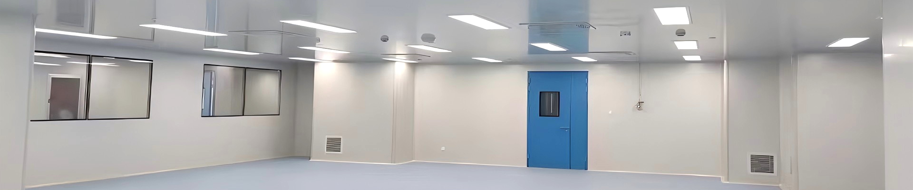
Cleanroom air cleanliness is the product of a filtration chain, but the final and most visible stage — the fan filter unit (FFU) — is what determines whether the controlled space actually holds its class. An FFU combines a fan, a HEPA or ULPA filter, and a housing into a single terminal module that both drives and cleans the supply airflow. The choice of fan technology and the way the unit is controlled have an outsized effect on energy consumption, airflow stability, and long-term operating cost.
SCT Cleanroom supplies EC (electronically commutated) fan filter units that pair a high-efficiency EC motor with a touch screen control panel, delivering intelligent control and measurable energy savings over conventional AC-driven units. This article explains what an EC FFU is, how the touch screen control panel changes operation, and why configuration decisions around layout, airflow, and maintenance access should be made before a single unit is installed.
1. What an EC FFU Brings to the Cleanroom
The defining difference between an EC FFU and a conventional AC FFU is the motor. An EC motor integrates the AC-to-DC conversion and the motor control electronics directly into the motor itself, eliminating the separate inverter or speed controller that an AC induction motor requires. This has three practical consequences for a cleanroom:
• Higher efficiency across the operating range: an EC motor maintains high efficiency even at partial speed, whereas an AC motor with a simple speed control loses efficiency as speed drops — and cleanroom FFUs operate at partial speed for much of their life
• Built-in speed control without an external VFD: the EC motor's integrated electronics accept a direct speed signal, reducing the component count, the wiring, and the failure points in each FFU
• Lower heat rejection into the airstream: less electrical loss becomes less heat added to the supply air, which reduces the load on the cleanroom's cooling system
For a cleanroom with dozens or hundreds of terminal FFUs running continuously, the efficiency advantage of EC motors compounds directly into lower electrical cost and a smaller HVAC cooling load over the life of the facility.
2. The Touch Screen Control Panel: Intelligent Operation, Not Just a Switch
The control interface of an FFU is where the cleanroom operator actually interacts with the airflow system. A conventional unit may be controlled by a simple switch or a remote dial, which limits the operator to turning the fan on or adjusting its speed blindly. A touch screen control panel changes the nature of that interaction:
2.1 What the Panel Displays and Controls
| Function | Capability | Operational Benefit |
| Fan speed / airflow | Direct numeric setpoint and live speed feedback | Precise airflow adjustment without guesswork |
| Filter pressure drop | Live differential pressure across the HEPA/ULPA filter | Scheduled filter replacement based on actual loading, not calendar time |
| Operating status | Run, alarm, and fault indication per unit | Immediate fault visibility without opening the ceiling |
| Group control | Group setpoint broadcast across multiple FFUs from a master panel | Consistent airflow across a zone without individual adjustment |
| Scheduling | Time-based speed profiles (e.g., reduced airflow during non-production hours) | Energy saving during unoccupied or reduced-activity periods |
| Alarm logging | Stored alarm and event history | Traceable records for maintenance and audit |
2.2 Energy-Saving Features Made Practical
The intelligent control capability of the touch screen panel is what turns the EC motor's efficiency potential into real energy savings. Two features are especially consequential:
• Setback scheduling: cleanrooms rarely require full airflow during non-production hours, cleaning periods, or maintenance windows; a scheduled setback profile that reduces fan speed during these periods saves energy without compromising cleanliness when production resumes
• Differential-pressure-based speed control: by monitoring the filter pressure drop, the system can compensate fan speed to hold a target airflow as the filter loads — preventing both under-delivery (which compromises cleanliness) and over-delivery (which wastes energy)
These features move the FFU from a constant-speed appliance to an actively managed component of the cleanroom's environmental control, which is where the energy-saving claim becomes concrete rather than nominal.
3. Planning the FFU Configuration: Layout, Airflow, and Access
The right equipment choice does not begin with the FFU itself. It begins with understanding how the controlled space will operate — and SCT works with project teams at that stage, before configuration is finalised. Three planning dimensions dominate the configuration decision:
3.1 Cleanroom Layout
FFU placement follows the cleanroom layout and the airflow pattern it is designed to achieve. Unidirectional (laminar) flow zones require a ceiling grid of FFUs sized and spaced to deliver a uniform face velocity across the entire protected area. Non-unidirectional (turbulent) zones may use fewer, strategically placed FFUs. The number, spacing, and orientation of FFUs are layout decisions that must be made before the ceiling grid and the supporting structure are fixed.
3.2 Airflow Requirements
The airflow delivered by the FFU array is determined by the cleanliness class and the air change rate it requires. A higher class demands more air changes, which means either more FFUs, higher individual airflow, or both. The EC FFU's ability to hold a precise setpoint across a range matters here: the units must be able to deliver the design airflow at the required face velocity while retaining headroom to compensate for filter loading over time.
3.3 Future Maintenance Access
An FFU that cannot be serviced without disrupting production is a liability. Configuration decisions must account for how the filter will be changed, how the motor will be reached, and how the unit will be accessed from the ceiling void or the room side. Filter replacement access, in particular, should be part of the upfront layout — not an afterthought discovered at the first scheduled change.
4. EC FFU Configuration Parameters
| Parameter | SCT Options | Selection Consideration |
| Fan technology | EC (electronically commutated) motor with integrated control electronics | High partial-load efficiency; no external inverter required |
| Filter | H14 HEPA (99.995% at 0.3 μm MPPS) standard; ULPA U15 option for ISO Class 4 and cleaner | Matches the terminal filtration requirement of the cleanroom class |
| Housing | Galvanised steel, powder-coated steel, or stainless steel 304/316L option | Corrosion resistance matched to the environment and cleaning regime |
| Airflow control | Touch screen panel; group control and setback scheduling | Precise and intelligent airflow management across the zone |
| Control interface | Local touch screen; RS485 / Modbus communication for BMS integration | Standalone or facility-integrated control |
| Service access | Room-side or ceiling-void filter access per project requirement | Maintenance without unnecessary production disruption |
5. Where EC FFUs Deliver the Strongest Payback
EC FFUs are not uniformly necessary across every cleanroom, but the following operating profiles favour the EC motor and intelligent control:
• Large FFU populations: in facilities with hundreds of terminal units, the per-unit efficiency advantage and the group-control capability multiply into a material annual energy saving
• Continuous or multi-shift operation: the more hours per year the FFUs run, the more the EC efficiency advantage and setback scheduling save
• Variable cleanliness demand: zones where airflow demand varies between production and non-production periods capture the full value of setback scheduling
• Temperature-sensitive processes: lower heat rejection into the supply air reduces the cooling load in precision environments
• Facilities with BMS integration: the RS485/Modbus interface allows the FFU array to participate in facility-wide energy and environmental control
6. Why SCT for EC FFU Solutions
SCT Cleanroom supplies EC fan filter units with touch screen control panels, and works with project teams from the layout stage to match the FFU configuration to the way the controlled space will actually operate:
• EC motor technology with integrated speed control and high partial-load efficiency
• Touch screen control panel with airflow setpoint, filter pressure monitoring, group control, setback scheduling, and alarm logging
• H14 HEPA as standard with ULPA U15 option for higher-class zones
• Housing and finish options — galvanised, powder-coated, or stainless steel — matched to the environment and cleaning regime
• RS485 / Modbus communication for integration with the facility's BMS
• Design-stage configuration support covering cleanroom layout, airflow requirements, and future maintenance access
Contact SCT Cleanroom to discuss your FFU requirements. Provide the cleanroom class, the layout, the airflow and air change requirements, and the access constraints, and SCT's technical team will recommend an EC FFU configuration with a full specification and quotation.
Frequently Asked Questions
Q1: What is the difference between an EC FFU and a conventional AC FFU?
The difference is in the motor. An EC (electronically commutated) motor integrates the AC-to-DC conversion and the speed control electronics into the motor itself, eliminating the external inverter that an AC induction motor requires. EC motors maintain high efficiency at partial speed — where cleanroom FFUs operate for much of their life — and reject less heat into the supply airstream. Both reduce energy cost and cooling load relative to a conventional AC unit.
────────────────────────────────────────────────────────────────────────────────
Q2: How does the touch screen control panel save energy?
The panel enables two energy-saving behaviours. First, setback scheduling reduces fan speed during non-production hours, cleaning periods, and maintenance windows, cutting energy when full airflow is not required. Second, differential-pressure-based speed control compensates the fan speed to hold a target airflow as the filter loads — preventing both under-delivery that compromises cleanliness and over-delivery that wastes energy. These turn the FFU from a constant-speed appliance into an actively managed component.
────────────────────────────────────────────────────────────────────────────────
Q3: Can multiple FFUs be controlled together?
Yes. Group control allows a setpoint to be broadcast from a master panel across multiple FFUs, keeping airflow consistent across a zone without individual adjustment. For larger facilities, the RS485/Modbus interface allows the FFU array to be integrated with the building management system for facility-wide energy and environmental control.
────────────────────────────────────────────────────────────────────────────────
Q4: How is FFU placement determined for a cleanroom?
Placement follows the cleanroom layout and the airflow pattern it must achieve. Unidirectional (laminar) flow zones require a ceiling grid of FFUs sized and spaced to deliver uniform face velocity across the protected area. Non-unidirectional zones may use fewer, strategically placed units. The number, spacing, and orientation are determined by the cleanliness class, the required air change rate, and the airflow uniformity needed — and should be fixed before the ceiling grid and supporting structure are finalised.
────────────────────────────────────────────────────────────────────────────────
Q5: Why should maintenance access be considered before FFU installation?
An FFU that cannot be serviced without disrupting production becomes a liability. Filter replacement and motor access must be planned at the layout stage, deciding whether access is from the room side or the ceiling void. Working access into the upfront configuration avoids discovering an impossible service path at the first scheduled filter change, when the cost of correction is highest.
Contact SCT Cleanroom
Website: www.sctcleanroom.com
Email: admin@sctcleanroom.com
WhatsApp: +86 15306200553
Post time: Nov-06-2026