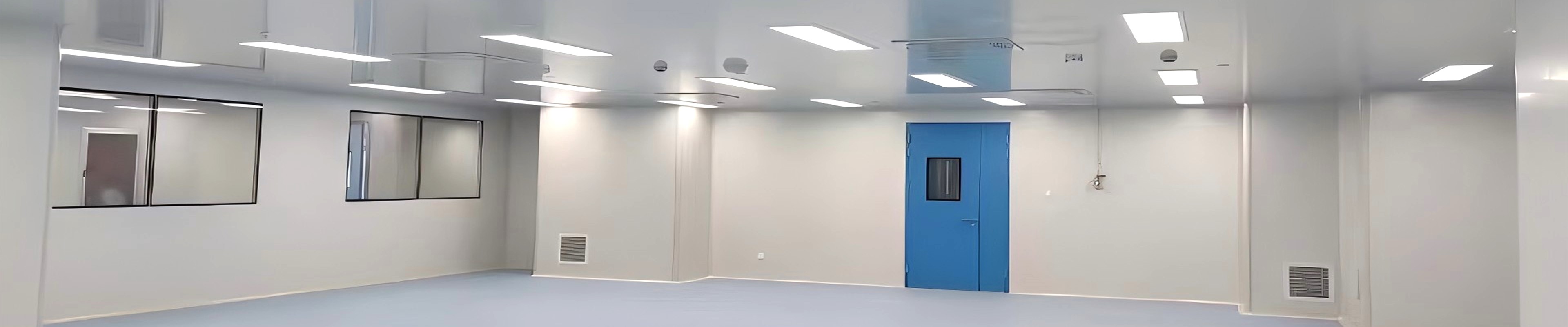
The cleanliness levels of clean rooms are divided into static levels such as class 10, class 100, class 1000, class 10000, class 100000, and class 300000. The majority of industries using class 100 clean rooms are LED electronics and pharmaceuticals. This article focuses on introducing the design scheme of using FFU fan filter units in class 100 GMP clean rooms.
The maintenance structure of clean room rooms is generally made of metal wall panels. After completion, the layout cannot be changed arbitrarily. However, due to the continuous updates of production processes, the original cleanliness layout of clean room workshop cannot meet the needs of new processes, resulting in frequent changes in the clean room workshop due to product upgrades, wasting a lot of financial and material resources. If the number of FFU units is increased or decreased, the cleanliness layout of the clean room can be partially adjusted to meet process changes. Moreover, the FFU unit comes with power, air vents, and lighting fixtures, which can save a lot of investment. This is almost impossible to achieve the same effect for a purification system that typically provides centralized air supply.
As a high-level air clean equipment, fan filter units are widely used in applications such as class 10 and class 100 clean rooms, clean production lines, assembled clean rooms, and local class 100 clean rooms. So how to install FFU in the clean room? How to carry out subsequent maintenance and upkeep?
FFU design solution
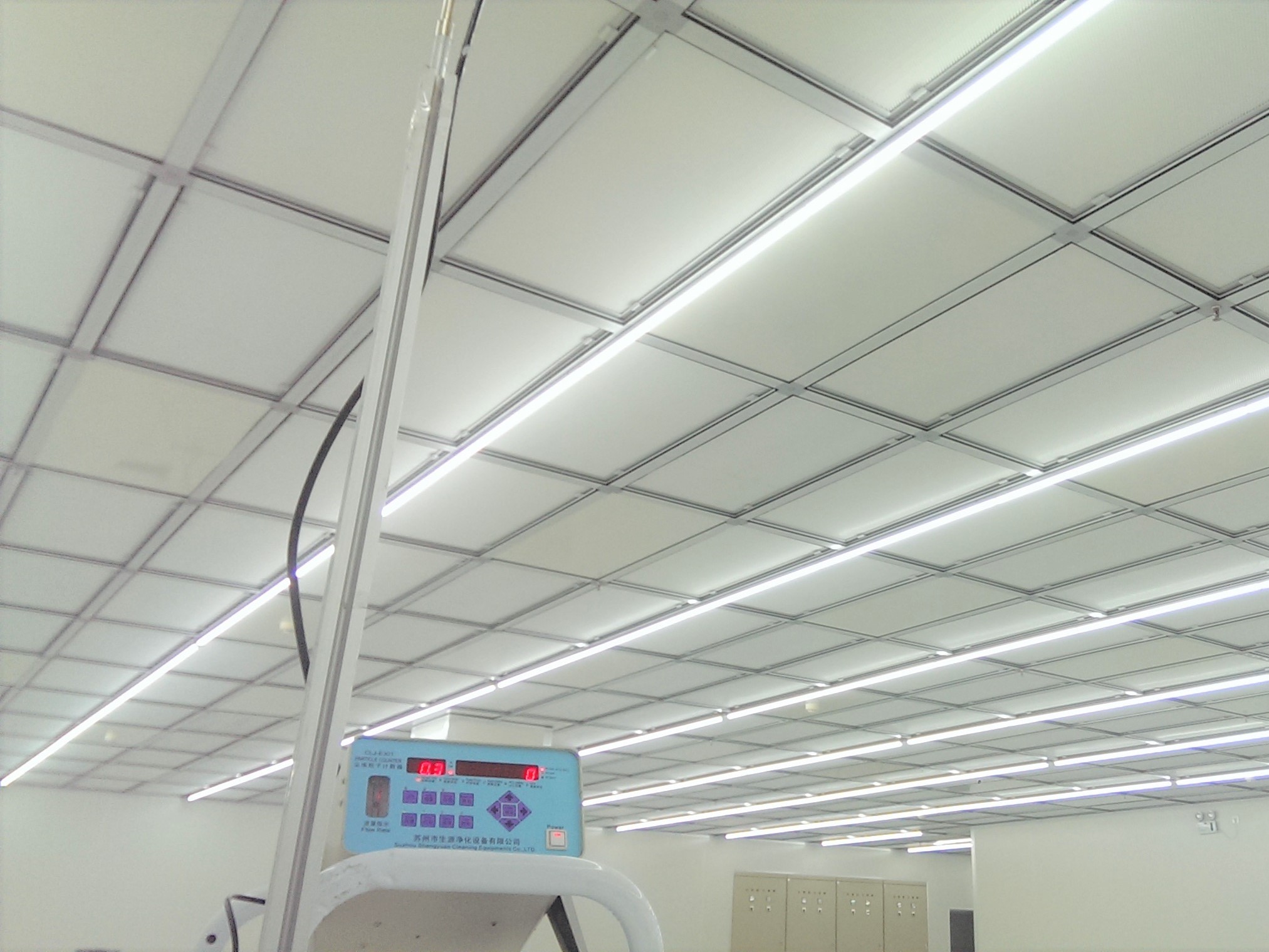
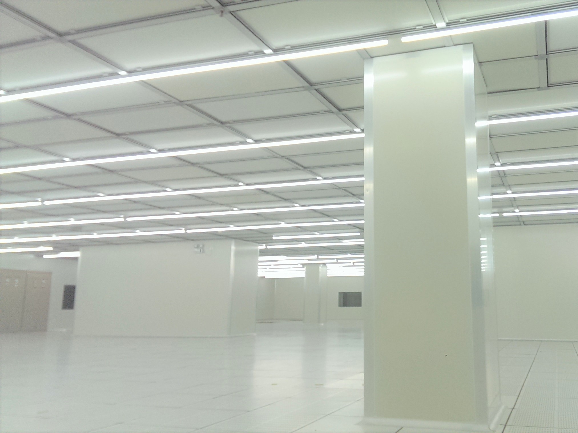
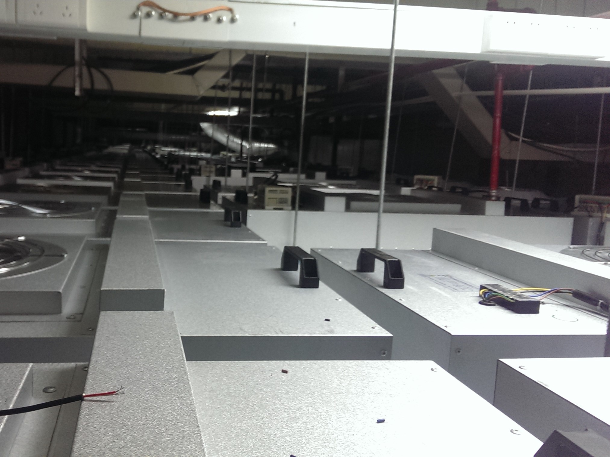
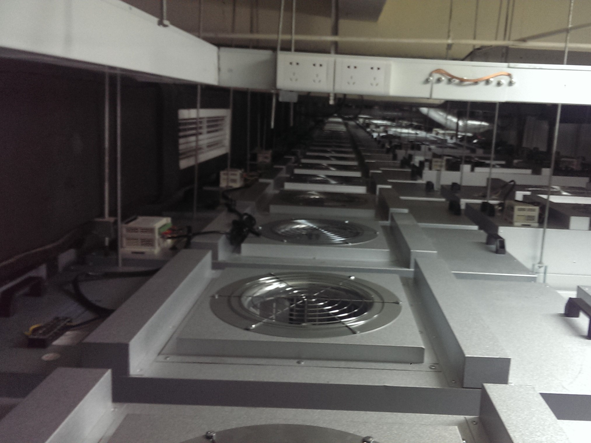
1. The suspended ceiling of the class 100 clean room is covered with FFU units.
2. Clean air enters the static pressure box through the elevated floor or vertical air duct at the lower part of the side wall in the class 100 clean area, and then enters the room through the FFU unit to achieve circulation.
3. The upper FFU unit in the class 100 clean room provides vertical air supply, and the leakage between the FFU unit and the hanger in the class 100 clean room flows indoors to the static pressure box, which has little impact on the cleanliness of the class 100 clean room.
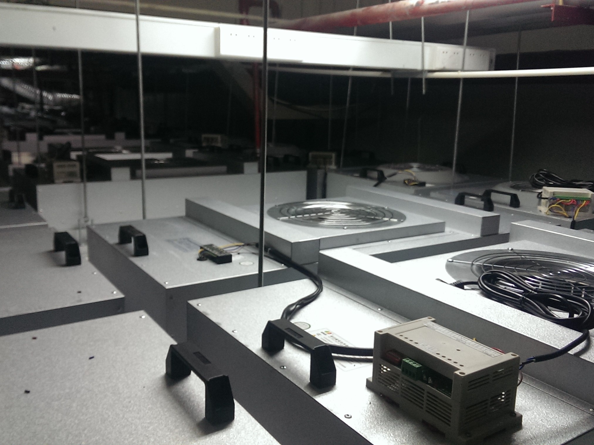
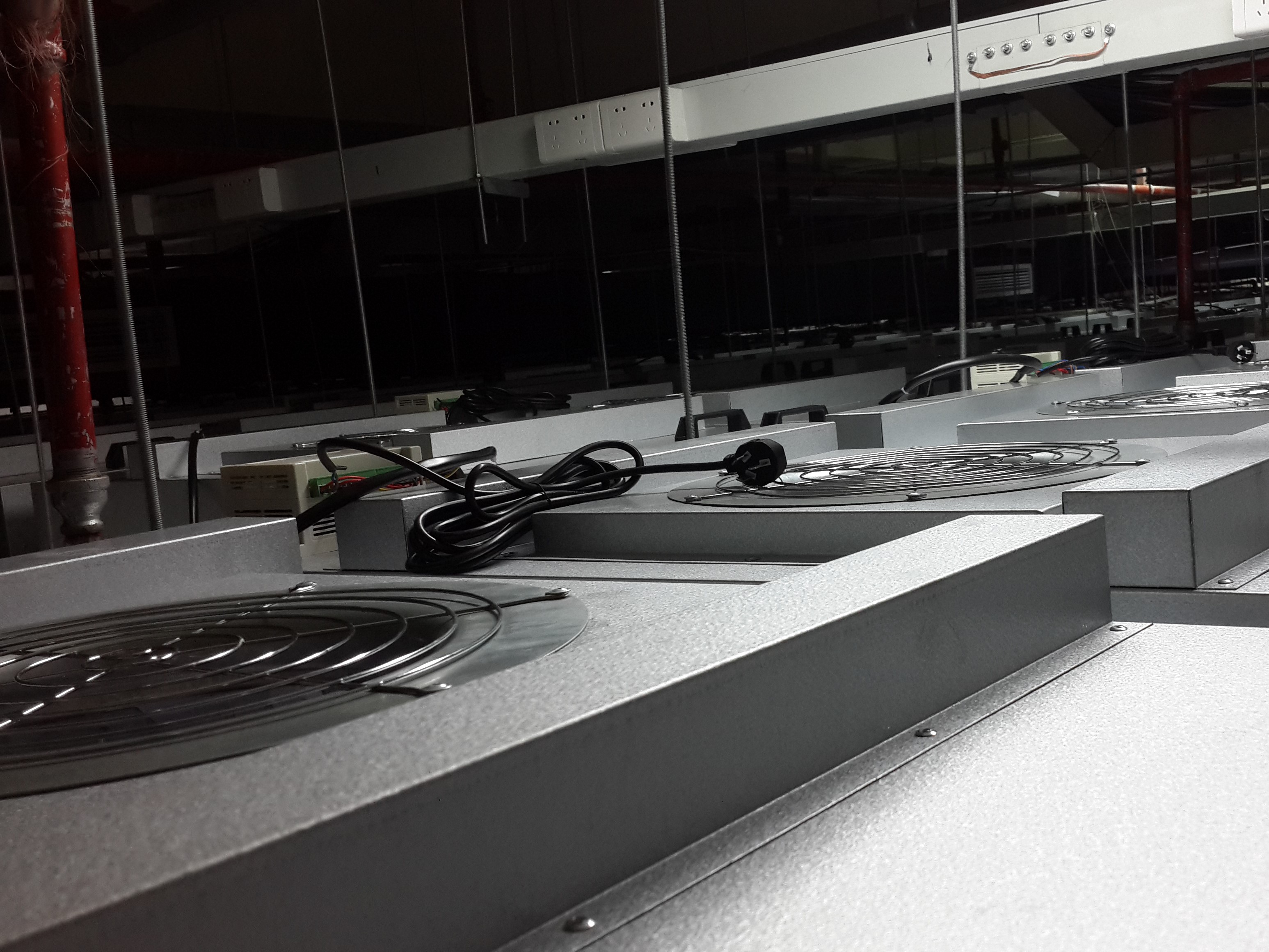
4. The FFU unit is lightweight and adopts a cover in installation method, making installation, filter replacement, and maintenance more convenient.
5. Shorten the construction cycle. The FFU fan filter unit system can save energy significantly, thus solving the shortcomings of centralized air supply due to the huge air conditioning room and the high operating cost of the air conditioning unit. The structural characteristics of FFU independence can be adjusted at any time to make up for the lack of mobility in the clean room, thus solving the problem that the production process should not be adjusted.
6. The use of FFU circulation system in clean rooms not only saves operating space, has high cleanliness and safety, low operating costs, but also has high operational flexibility. It can be upgraded and adjusted at any time without affecting production, which can well meet the needs of clean rooms. Therefore, the use of FFU circulation system has gradually become the most important clean design solution in semiconductor or other manufacturing industries.
FFU hepa filter installation conditions
1. Before installing the hepa filter, the clean room must be thoroughly cleaned and wiped. If there is dust accumulation inside the purified air conditioning system, it should be cleaned and wiped again to meet the cleaning requirements. If a high-efficiency filter is installed in the technical interlayer or ceiling, the technical interlayer or ceiling should also be thoroughly cleaned and wiped.
2. When installing, the clean room must be already sealed, the FFU must be installed and started to operate, and the purification air conditioning must be put into trial operation for more than 12 hours of continuous operation. After cleaning and wiping the clean room again, install the high-efficiency filter immediately.
3. Keep the clean room clean and dust-free. All keels have been installed and leveled.
4. Installation personnel must be equipped with clean clothes and gloves to prevent human contamination of the box and filter.
5. To ensure the long-term effective operation of hepa filters, the installation environment should not be in oil fumes, dusty, or humid air. The filter should avoid contact with water or other corrosive liquids as much as possible to avoid affecting its effectiveness.
6. It is recommended to have 6 installation personnel per group.
Unloading and handling FFUs and hepa filters and precautions
1. The FFU and hepa filter have undergone multiple protective packaging before leaving the factory. Please use a forklift to unload the entire pallet. When placing goods, it is necessary to prevent them from tipping and avoid severe vibrations and collisions.
2. After unloading the equipment, it should be stored indoors in a dry and ventilated place for temporary storage. If it can only be stored outdoors, it should be covered with tarpaulin to avoid rain and water ingress.
3. Due to the use of ultra-fine glass fiber filter paper in hepa filters, the filter material is prone to breakage and damage, resulting in particle leakage. Therefore, during the process of unpacking and handling, it is not allowed to dump or crush the filter to prevent severe vibration and collision.
4. When removing the hepa filter, it is prohibited to use a knife or sharp object to cut the packaging bag to avoid scratching the filter paper.
5. Each hepa filter should be handled by two people together. The operator must wear gloves and handle it gently. Both hands should hold the filter frame, and it is prohibited to hold the filter protective net. It is prohibited to touch the filter paper with sharp objects, and it is prohibited to twist the filter.
6. Filters cannot be placed in layers, they should be arranged horizontally and orderly, and placed neatly against the wall in the installation area waiting for installation.
FFU hepa filter installation precautions
1. Before installing an hepa filter, the appearance of the filter must be inspected, including whether the filter paper, sealing gasket, and frame are damaged, whether the size and technical performance meet the design requirements. If the appearance or filter paper is severely damaged, the filter should be prohibited from installation, photographed, and reported to the manufacturer for treatment.
2. When installing, only hold the filter frame and handle it gently. To prevent severe vibration and collision, it is strictly prohibited for installation personnel to touch the filter paper inside the filter with their fingers or other tools.
3. When installing the filter, pay attention to the direction, so that the arrow on the filter frame marks outward, that is, the arrow on the outer frame should be consistent with the airflow direction.
4. During the installation process, it is not allowed to step on the filter protection net, and it is prohibited to discard debris on the surface of the filter. Do not step on the filter protection net.
5. Other installation precautions: Gloves must be worn and fingers must be cut on the box. The FFU installation should be aligned with the filter, and the edge of the FFU box should not be pressed on top of the filter, and it is prohibited to cover items on the FFU; Do not step on the FFU intake coil.
FFU hepa filter installation process
1. Carefully remove the hepa filter from the shipping packaging and check for any component damage during transportation. Remove the plastic packaging bag and place the FFU and hepa filter in a clean room.
2. Install the FFU and hepa filter on the ceiling keel. At least 2 people should prepare on the suspended ceiling where the FFU is to be installed. They should transport the FFU box to the installation position under the keel, and another 2 people on the ladder should lift the box. The box should be at a 45 degree angle to the ceiling and pass through it. Two people on the ceiling should hold the FFU handle, take the FFU box and lay it flat on the nearby ceiling, waiting for the filter to be covered.
3. Two people on the ladder received the hepa filter handed over by the mover, holding the frame of the hepa filter with both hands at a 45 degree angle to the ceiling, passing through the ceiling. Handle with care and do not touch the surface of the filter. Two people take over the hepa filter on the ceiling, align it with the four sides of the keel and lay it down in parallel. Pay attention to the wind direction of the filter, and the air outlet surface should face downwards.
4. Align the FFU box with the filter and place it down around it. Handle it gently, taking care not to let the edges of the box touch the filter. According to the circuit diagram provided by the manufacturer and the buyer's electrical regulations, connect the fan unit to an appropriate voltage power supply using a cable. The system control circuit is connected by group based on the grouping plan.
FFU strong and weak current installation requirements and procedures
1. In terms of strong current: The input power supply is a single-phase 220V AC power supply (live wire, ground wire, zero wire), and the maximum current of each FFU is 1.7A. It is recommended to connect 8 FFUs to each main power cord. The main power cord should use 2.5 square millimeters of copper core wire. Finally, the first FF can be connected to a strong current bridge using a 15A plug and socket. If each FFU needs to be connected to a socket, a copper core wire of 1.5 square millimeters can be used.
2. Weak current: The connection between the FFU collector (iFan7 Repeater) and the FFU, as well as the connection between the FFUs, are all connected using network cables. The network cable requires AMP Category 6 or Super Category 6 shielded network cable, and the Registered jack is AMP shielded Registered jack. The suppression order of network lines from left to right is orange white, orange, blue white, blue, green white, green, brown white, and brown. The wire is pressed into a parallel wire, and the pressing sequence of the Registered jack at both ends is the same from left to right. When pressing the network cable, please pay attention to fully contact the aluminum sheet in the network cable with the metal part of the Registered jack to achieve the shielding effect.
3. Precautions during the connection process of power and network cables. In order to ensure a strong connection, single core copper wire needs to be used, and there should be no exposed parts after the wire is inserted into the connection terminal. To prevent leakage and reduce the impact on data transmission, FFUs must take grounding measures. Each group must be a separate network cable, and cannot be mixed between groups. The last FFU in each zone cannot be connected to FFUs in other zones. The FFUs within each group must be connected in order of address numbers to facilitate FFU fault detection, such as G01-F01=>G01-F02=>G01-F03=> G01-F31.
4. When installing power and network cables, brute force should not be exerted, and the power and network cables should be fixed to prevent them from being kicked off during construction; When routing strong and weak current lines, it is necessary to avoid parallel routing as much as possible. If the parallel routing is too long, the spacing should be more than 600mm to reduce interference; It is prohibited to have the network cable too long and bundle it with the power cable for wiring.
5. Pay attention to protecting FFU and filter during the construction on interlayer, keep the surface of the box clean, and prevent water from entering the FFU to avoid damaging the fan. When connecting the FFU power cord, power should be cut off and attention should be paid to preventing electric shock caused by leakage; After all FFUs are connected to the power cord, a short-circuit test must be carried out, and the power switch can be turned on only after the test is passed; When replacing the filter, the power must be turned off before proceeding with the replacement operation.
Post time: Jul-27-2023