
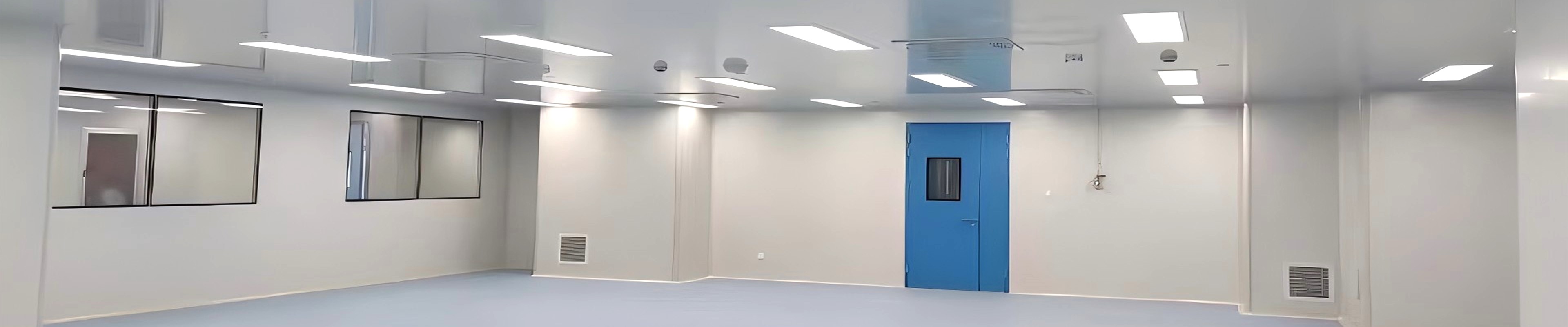
In most cleanrooms, clean air is a two-part problem. The air must be filtered to remove particles, and it must be moved — in the right direction, at the right velocity — so that filtered air actually reaches the point of work. A fan filter unit (FFU) solves both jobs in one compact, ceiling-mounted module: a motor-driven fan that circulates air through a HEPA or ULPA filter and pushes it downward as a uniform column of clean air.
This self-contained design is what makes the fan filter unit the default building block for cleanrooms that need flexible ceiling layouts and consistent airflow support. Whether the environment is electronics, pharmaceutical, laboratory or precision manufacturing, the FFU lets engineers configure — and later reconfigure — an entire clean air supply without ductwork, without a central air handling unit, and without committing the ceiling to a fixed layout.
This article explains how an FFU combines filtration and air circulation into one unit, why that unlocks flexible ceiling layouts, how it holds airflow consistent, and how to specify one for the four core applications.
FFU at a Glance
| Parameter | Typical Specification | Why It Matters |
| Filtration + circulation | Centrifugal fan + H14 HEPA + G4 pre-filter in one housing | One module replaces duct + terminal filter |
| HEPA efficiency | H14 ≥99.99% @ 0.3 μm (H13 / U15 optional) | Meets ISO 5 / Grade A needs |
| Face velocity | 0.30–0.50 m/s, adjustable | Sets the laminar downflow regime |
| Housing sizes | 600×600 to 1200×1200 mm | Matches standard ceiling T-grid bars |
| Airflow uniformity | ±15% across the filter face | Consistent protection, no dead zones |
| Installation | Drop-in ceiling module, no ductwork | Flexible, reconfigurable layouts |
| Applications | Electronics, pharma, laboratory, precision manufacturing | Broad ISO 5–8 coverage |
1. One Module, Two Jobs: What an FFU Actually Does
Traditionally, a cleanroom gets its clean air from a chain of separate equipment: an air handling unit that conditions and pressurises the air, a network of ducts that carries it to the ceiling, and a terminal HEPA filter that does the final polishing. Every joint in that chain is a pressure drop, a leak risk and a maintenance point — and the whole system is locked to wherever the ducts were originally run.
An FFU collapses that chain. Each unit is a self-powered, plug-and-place module that draws room air in, filters it to HEPA or ULPA standard, and discharges it downward — no central fan, no ductwork, no external static pressure required. Because every module is autonomous, an array of FFUs becomes the ceiling itself: add a unit, move a unit, or partition a zone without touching a single duct.
2. How an FFU Combines Filtration and Air Circulation
Inside one compact housing, an FFU performs two engineering jobs in series. Understanding each stage is what separates a well-specified unit from one that looks identical on a datasheet.
Filtration stage
Return air first passes through a coarse G4 pre-filter, which traps fibres, dust agglomerates and large debris before they reach the main filter. This pre-filter is field-replaceable from the cleanroom side and extends the main HEPA media life by an estimated 40–60%. The polished filtration then happens at the HEPA or ULPA stage: an H14 filter removes at least 99.99% of particles at 0.3 μm (the most penetrating particle size), which is the level required to hold ISO 5 / Grade A conditions at the working plane.
Air circulation stage
The motive force is a motor-driven centrifugal impeller mounted inside the housing. It pressurises the plenum above the filter, forcing air through the media and out the discharge face as a uniform piston of clean air. Because the fan and the filter are matched as one system, the face velocity — typically 0.30 to 0.50 m/s — stays stable across the entire filter face, which is what produces the laminar downflow that sweeps particles away from the work zone.
The result is a closed-loop, ceiling-level recirculation system. To see how an FFU system scales from a single module to a full ceiling array with returns and balancing, review the layout design methodology behind a complete installation.
3. Why FFUs Unlock Flexible Ceiling Layouts
The flexibility of an FFU comes from what it removes: the fixed relationship between an air handler and a specific ceiling location. A ducted terminal system is designed once and is expensive to change — moving a diffuser means rebalancing duct static pressures, and expanding the cleanroom often means a new AHU calculation.
An FFU ceiling, by contrast, is a grid of identical, independently powered modules. Three practical freedoms follow. First, zoning: engineers can cover the full ceiling for a whole-room ISO 5 environment, or place FFUs only over critical workstations while the rest of the room runs at a lower class. Second, reconfiguration: when a production line moves, the FFUs move with it — lift a module out of the T-grid and drop it into a new position. Third, phased expansion: adding capacity is a matter of adding modules, not re-engineering ductwork.
This is why FFUs are the standard choice for facilities where the layout is expected to evolve — pilot lines that scale up, R&D suites that are regularly re-tooled, and multi-product factories where a single shell hosts several different clean zones over its life.
4. How an FFU Holds Airflow Consistent
A cleanroom is only as clean as its weakest airflow point. If one part of the ceiling delivers 0.50 m/s and another delivers 0.25 m/s, the slow zone becomes a particle trap. The FFU addresses this at two levels.
At the module level, the discharge face is fitted with a perforated diffuser plate or screen that equalises velocity across the entire filter area. The result is airflow uniformity within ±15% across any 30 cm × 30 cm measurement grid — the tolerance prescribed by IEST-RP-CC002.4 for laminar-flow work zones. At the array level, per-unit speed controllers allow each module to be trimmed during commissioning so the whole ceiling delivers a balanced, consistent downflow.
For larger installations, networked control removes the manual balancing step entirely. An intelligent FFU links modules over RS-485 Modbus so airflow setpoints, filter pressure-drop trends and alarms are managed from a single BMS workstation — a requirement for validated facilities that need to prove consistent conditions over time.
5. Where FFUs Are Applied: Four Environments
The same FFU architecture serves four very different industries. What changes between them is the target cleanliness class, the ceiling coverage, and the level of control and validation.
Electronics and semiconductor
Wafer fabrication, microelectronics assembly and flat-panel production demand ISO 5–7 conditions with a stable, uniform downflow to prevent particle deposition on sensitive surfaces. Full-ceiling FFU arrays deliver the laminar regime these processes require, and their modularity supports the fast-moving, frequently re-tooled nature of electronics fabs.
Pharmaceutical and aseptic processing
In pharmaceutical manufacturing, FFUs create the localised Grade A laminar-flow zones required over aseptic filling and stopper-bowl areas, nested inside a lower-class background room. When coupled with networked control and an environmental monitoring system, an intelligent FFU supports the data-integrity and audit-trail expectations of EU GMP Annex 11 and 21 CFR Part 11. For the compliance framework around these installations, see the guide to cleanroom GMP validation.
Laboratory and research
Research laboratories, cell-culture suites and biosafety rooms are among the most frequently reconfigured clean spaces in any facility. An FFU ceiling lets a laboratory move its clean zones as experiments and equipment change, without the cost of re-routing ductwork — a decisive advantage for academic and contract-research environments that re-plan their bench layouts season to season.
Precision manufacturing
Optics, MEMS, medical devices and high-precision assembly rely on ISO 6–8 cleanliness with consistent airflow over the assembly line. Here the FFU's value is consistency and coverage: a uniform downflow protects sensitive components from airborne particles and — combined with proper grounding — supports static control during assembly.
Across all four environments, the FFU is part of a larger clean room equipment ecosystem that includes pass boxes, air showers and HEPA terminal housings. For a direct comparison of when to choose one approach over another, see the guide to HEPA box vs. fan filter unit.
6. Specifying an FFU: Six Parameters That Decide Performance
Two FFUs can look identical and perform very differently. The six parameters below are where the differences live, and where a specification should be explicit.
| Parameter | What to Specify | Typical SCT Range |
| Fan motor type | AC (induction) vs. EC (electronically commutated); EC saves energy at partial load | AC standard, EC optional |
| Filter class | H13, H14 or U15 efficiency to match the target ISO / GMP class | H14 standard (99.99% @ 0.3 μm) |
| Face velocity & airflow | m/s and m³/h at the working plane, adjustable or fixed | 0.30–0.50 m/s, 5-step or stepless |
| Housing size & material | Footprint to match the ceiling grid; galvanized steel or stainless | 600×600 to 1200×1200 mm; SS optional |
| Noise level | dB(A) at 1 m below the filter face, at rated velocity | ≤46 dB(A) at 0.45 m/s |
| Control | Standalone speed controller vs. networked RS-485 monitoring | Standalone standard, intelligent optional |
For projects that need certified hardware for regulated industries, the CE-standard clean room FFU is a useful reference for a unit built and documented to Machinery and EMC directive expectations.
7. Frequently Asked Questions About Fan Filter Units
Q: What is a fan filter unit (FFU)?
A: An FFU is a self-contained, ceiling-mounted clean air module that combines a motor-driven fan, a HEPA or ULPA filter and a pre-filter in one compact housing. It draws air in, filters it and discharges it downward as a uniform column of clean air — no central air handler or ductwork required.
Q: How does an FFU combine filtration and air circulation?
A: The fan pressurises the plenum above the filter, forcing return air through a G4 pre-filter and then a HEPA/ULPA main filter, then out the discharge face at a controlled face velocity (typically 0.30–0.50 m/s). Filtration and air movement happen in series inside a single module.
Q: Why are FFUs better than ducted terminal HEPA systems for flexible layouts?
A: Because each FFU is independent and drop-in. Units can be added, moved or re-zoned by repositioning modules in the ceiling grid, without re-engineering ductwork or rebalancing a central air handler — ideal for facilities whose layout will evolve.
Q: What cleanroom classes can an FFU support?
A: An H14-equipped FFU supports ISO 5 (Class 100) conditions at the working plane, and the same architecture serves ISO 6–8 rooms by adjusting ceiling coverage and airflow. Full-ceiling arrays give whole-room laminar flow; partial coverage creates localised clean zones.
Q: How is consistent airflow maintained across an FFU ceiling?
A: A perforated diffuser plate equalises velocity across the filter face (typically within ±15%), and per-unit speed controllers allow the whole array to be balanced at commissioning. Networked (intelligent) FFUs automate this with per-unit setpoints and monitoring.
Q: Which industries use fan filter units?
A: Electronics and semiconductor manufacturing, pharmaceutical and aseptic processing, laboratories and research facilities, and precision manufacturing (optics, MEMS, medical devices) all use FFUs for flexible, consistent clean air supply.
8. Why SCT Cleanroom for Your FFU Ceiling?
SCT Cleanroom designs and manufactures fan filter units and the cleanroom equipment around them, and has supplied clean air solutions to more than 200 clients across 50 countries since 2005. Three things distinguish the approach:
• Matched fan-and-filter design. Motor, impeller and filter media are specified as one system, so face velocity and airflow uniformity are achieved out of the box rather than chased during commissioning.
• Modular, flexible delivery. Standard sizes from 600×600 to 1200×1200 mm drop into common ceiling grids, with galvanized or stainless steel housings and standalone or networked control options.
• Application-matched specification. SCT specifies each unit against the target ISO or GMP class and the application — electronics, pharmaceutical, laboratory or precision manufacturing — rather than offering a single generic model.
Build a Ceiling That Can Change
A fan filter unit is more than a fan and a filter bolted together. It is a decision about how flexible your cleanroom will be — whether the clean air supply is locked to a fixed duct layout, or whether it can be re-zoned, expanded and rebalanced as the process changes. For electronics, pharmaceutical, laboratory and precision manufacturing environments alike, that flexibility is what keeps a cleanroom investment useful for its full life.
SCT Cleanroom can help you size the FFU array, specify the right filter class and control architecture, and lay out a ceiling that delivers consistent airflow today and adapts tomorrow. Contact us to start a technical review of your project.
Contact SCT Cleanroom Today
Website: www.sctcleanroom.com
Email: admin@sctcleanroom.com
WhatsApp: +86 15306200553
Post time: Aug-25-2026